I am delighted to be able to share some of the imagery showing the design of the olfactometer as it currently stands. Hopefully these pictures are worth a thousand words, as today’s blog post is intended to be quite short…
The material being used for the panels and tubing which make the parts illustrated is transparent, colourless, acrylic. The pin which for the hinge and handle for the rotating doors in the mosquito trap/release chambers is stainless steel, as is the mesh which covers the ends and surface of the gate.
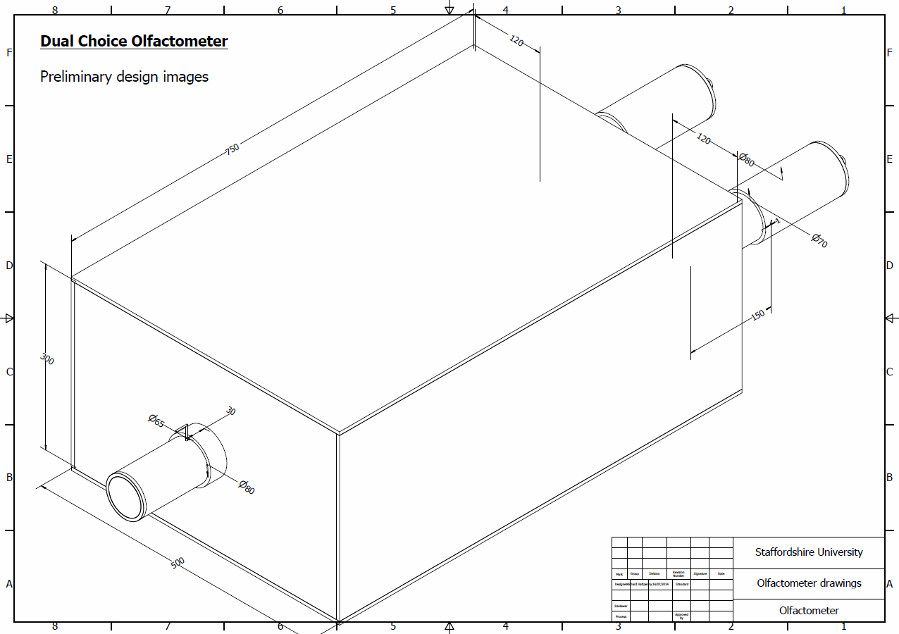
3 dimensional drawing of the proposed olfactometer experimental chamber.
With reference to the 3 dimensional diagram above, the air will be blown into the ports at the rear of the unit, where they will pass through the 2 variable chambers. Here the air will flow over the variable/s being tested (or the control), where it will become ‘loaded’ with chemicals which may or may not cause a behavioural change in the mosquitoes. The air will then flow through the main flight chamber before exiting through the mosquito release chamber at the front of the unit.
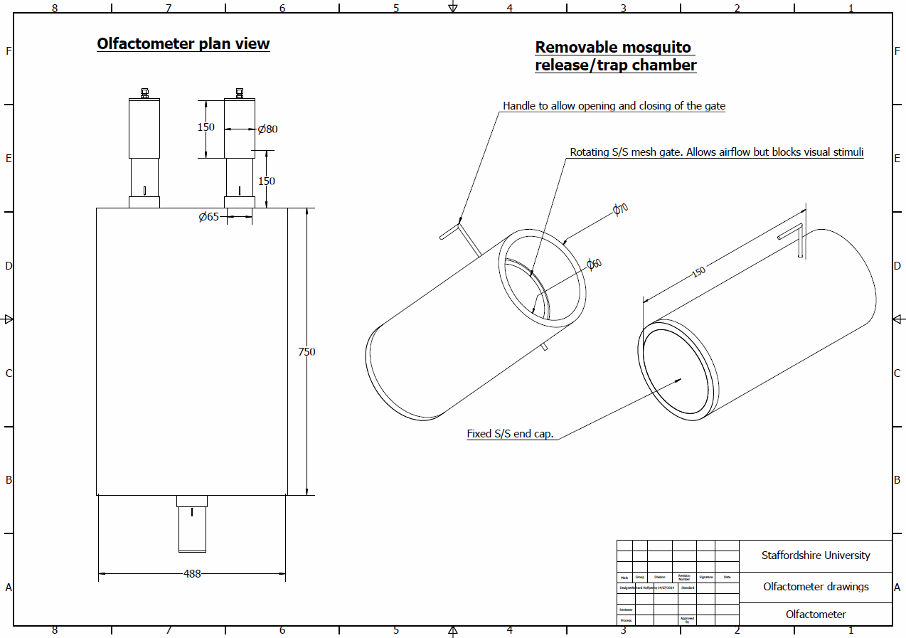
Plan view of the experimental chamber. 3 dimensional drawings of the proposed olfactometer mosquito release/traps chambers.
There are a few design points which are currently still under discussion; such as the design of the rotating gates in the mosquito trap/release chambers. Currently they are designed as an acrylic ring which has a stainless steel mesh across it, there is some suggestion that it may be easier to simply use an acrylic disk and drill this through with many small holes. This is the potential drawback that the drilled holes will not provide a visual barrier to the stimulus being offered, where the stainless steel mesh is opaque and will therefore help control against the mosquitoes being able to see rather that smell the stimuli.
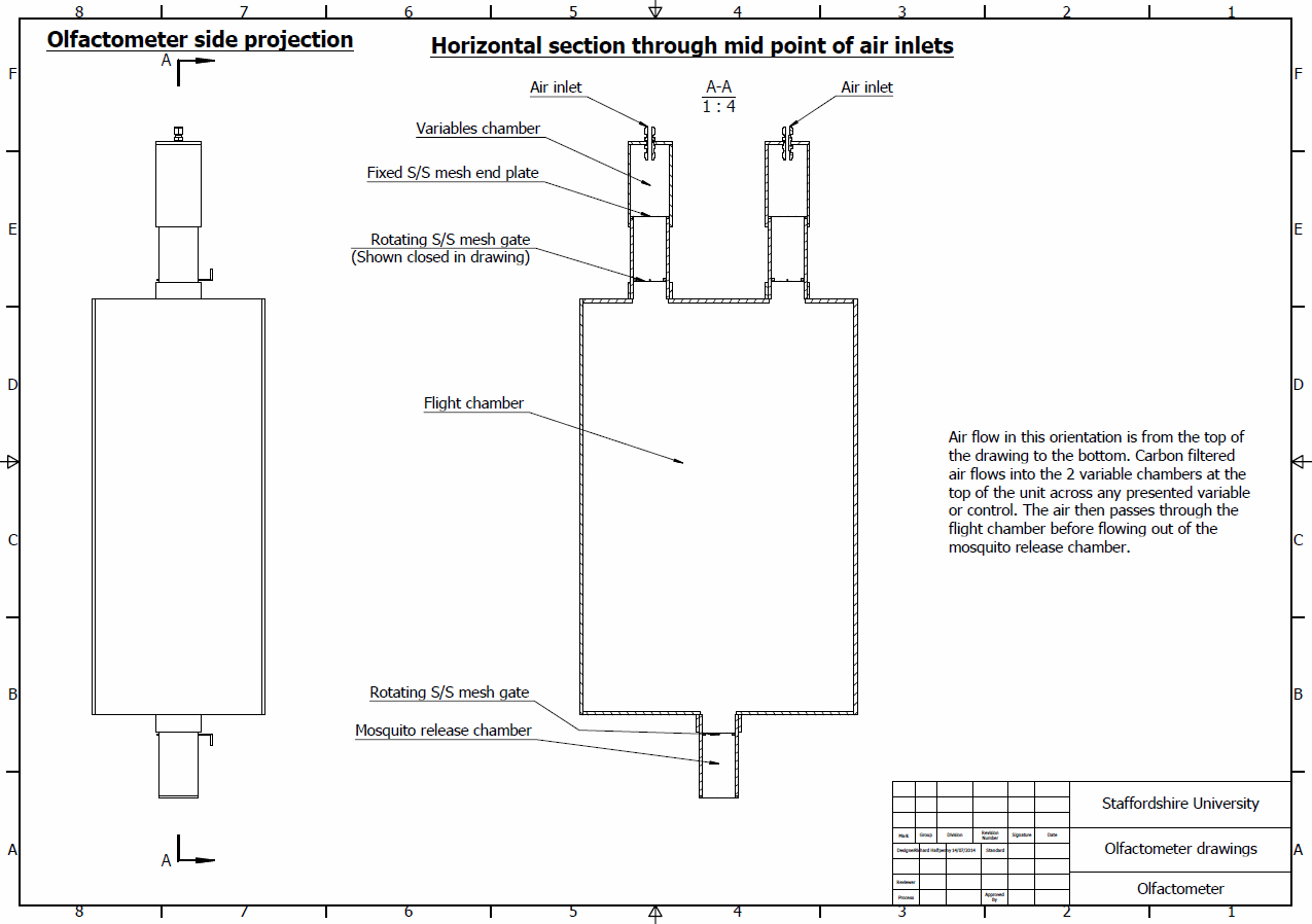
Side view of the experimental chamber, showing plane for sectional diagram to the right.
The airflow inlets shown in sectional view in the 3rd drawing are slightly misrepresented in the drawing. The internal portion, that which is inside the chamber, is actually shorter than shown. This will be adjusted in the next round of design reviews.
As always comments and questions are greatly appreciated!
Hi Rich,
After our recent email correspondence and subsequent meetings, I have uploaded some 3d animations of the olfactometer to the shared drive for your consideration.
Hope that they are ok for your needs.
All the best
Dave
Hi Dave,
Thanks for doing these. I’ve checked the folder and can see the uploads. I’ll process these and upload them to the blog as soon as I can.
Thanks again,
Rich