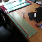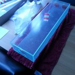
With the build completed I moved the olfactometer into the insectary for testing and commissioning. This was quite an exciting time as I was getting closer to the moment of truth. Would the equipment, that had thus far lived in my head and in computer software, be fit for purpose. Would the careful design, modelling and building pay off and furnish me with kit that would be central to my study of mosquito olfactory mediated behaviour, or would it leave me scratching my head on the way back to the drawing board.
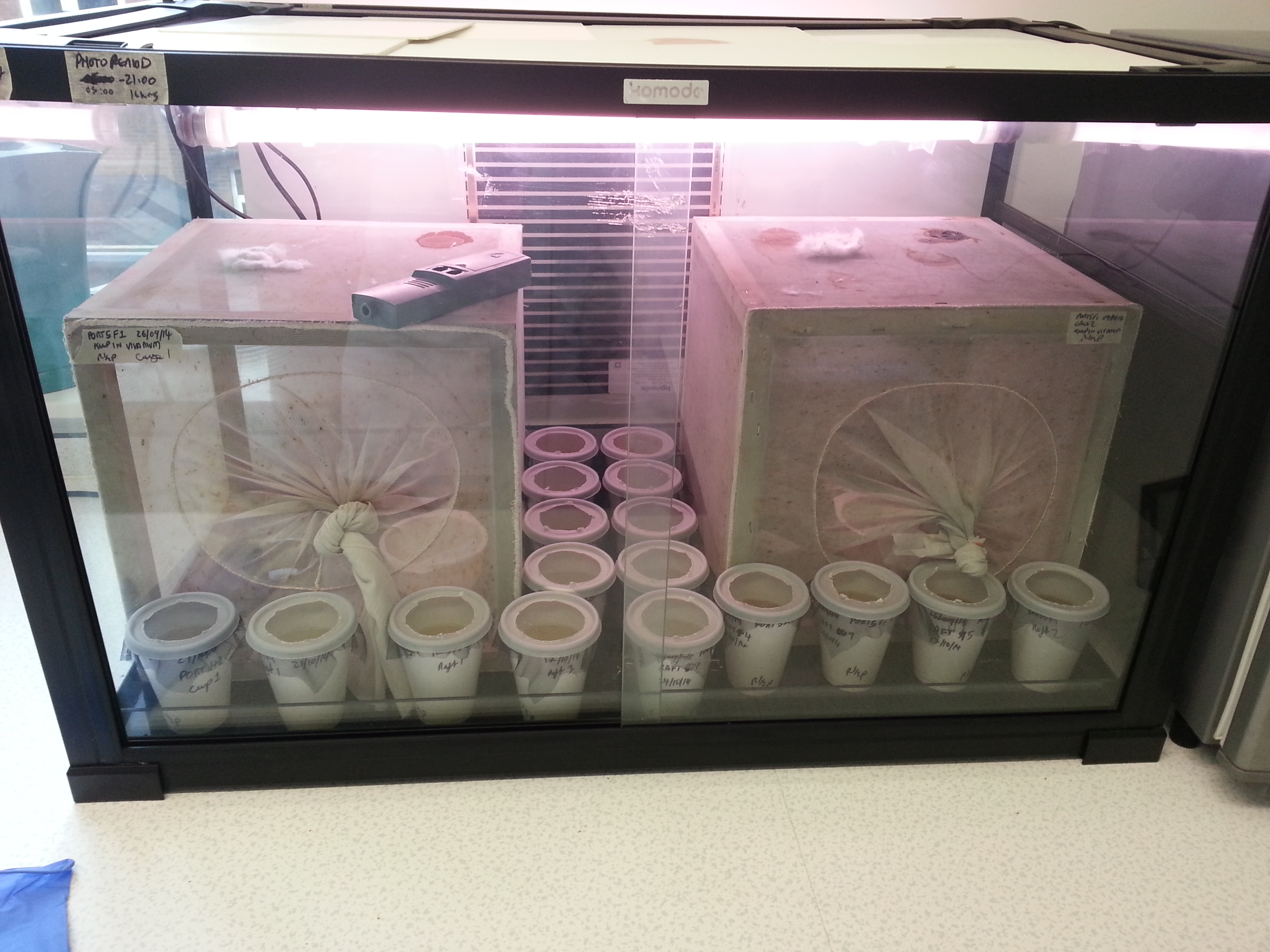
Hurrying the development of the soon to be experimental candidate mosquitoes. Preconditioning for temperature and light cycle.
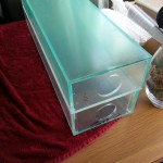
Once all the connections has been made to the newly purchased air compressor, carbon filter, inline heater and humidifier it was time to check that it was capable of delivering steady air flow at the right temperature and humidity.
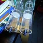
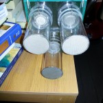
Air flow was a simple matter of setting the litres per minute to match the modeled input. The humidity and temperature required a little more finesse, as it required a balancing of the water volume and temperature in the humidifier; once set, however, it remained steady at 25 degrees centigrade and 75 % relative humidity.
Importantly, I was unable to find any airflow bias between the trap chambers and variable delivery chambers, meaning that I could move on to the next step – a live run with mosquitoes.