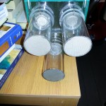
Testing and commissioning the dual-choice olfactometer

With the build completed I moved the olfactometer into the insectary for testing and commissioning. This was quite an exciting time as I was getting closer to the moment of truth. Would the equipment, that had thus far lived in my head and in computer software, be fit for purpose. Would the careful design, modelling and building pay off and furnish me with kit that would be central to my study of mosquito olfactory mediated behaviour, or would it leave me scratching my head on the way back to the drawing board.

Hurrying the development of the soon to be experimental candidate mosquitoes. Preconditioning for temperature and light cycle.

Hurrying the development of the soon to be experimental candidate mosquitoes. Preconditioning for temperature and light cycle.

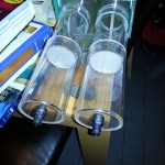
Once all the connections has been made to the newly purchased air compressor, carbon filter, inline heater and humidifier it was time to check that it was capable of delivering steady air flow at the right temperature and humidity.

Air flow was a simple matter of setting the litres per minute to match the modeled input. The humidity and temperature required a little more finesse, as it required a balancing of the water volume and temperature in the humidifier; once set, however, it remained steady at 25 degrees centigrade and 75 % relative humidity.

Importantly, I was unable to find any airflow bias between the trap chambers and variable delivery chambers, meaning that I could move on to the next step – a live run with mosquitoes.


Building the olfactometer!

After a long digital design and modelling process I was delighted to finally have all the component parts in hand and ready to assemble. In the interest of working uninterrupted, I chose to carry out the construction at home rather than in the lab. Hence the dining table, and occasional clutter you’ll see in these images.

Due to the late design changes after the computational fluid dynamic modelling of the previous iteration I had enough acrylic sheet to build 2 main flight chambers rather than  one. Since the build this has proven fortuitous as it means I can carry out twice as many behavioural assays at the same time. This is particularly important as my study mosquitoes require overnight assays which makes time a real limiting factor.

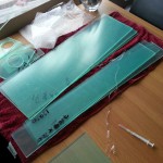
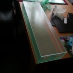
If you could buy a flat-pack dual choice olfactometer this is what it might look like

If you could buy a flat-pack dual choice olfactometer this is what it might look like. (N.B. the syringe is for applying the acrylic cement)

Acrylic is quite nice to work with as the “glue” is very watery and so provide you can get a tight bond between surfaces you can apply the glue in one place and allow capillary action to draw it in and fill the void.

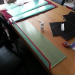
Insulating tape was used to hold the pieces in place whilst the glue was applied and set. Because

Insulating tape is slightly elastic it is great for this as it can be pulled very tight and allowed to relax again; once relaxed the acrylic sheet is held securely but not deformed.

Insulating tape is slightly elastic it is great for this as it can be pulled very tight and allowed to relax again; once relaxed the acrylic sheet is held securely but not deformed.

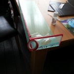
Also, because the edges were very nearly square, after the laser cutting, forming the box was easier than I feared it might be.

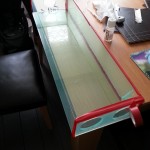
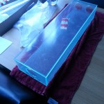
Once the insulating tape was removed I was left with something remarkably similar to the design!

Once the insulating tape was removed I was left with something remarkably similar to the design!

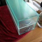
The gallery below shows the stages of construction before moving the units back to the laboratory.

In the next blog post I’ll look back over the installation and first test assays using this dual choice olfactometer.

Flight chamber design is now finalised.

Following a number of different design versions I am pleased to have settled on a final version that is going forward to prototyping.

The biggest, most obvious, change is the size of the flight chamber. This is significantly reduced in cross sectional area in response to the computational fluid dynamic work that has been carried-out. The reduced area leads to a reduction of required air volume needed to generate the flow rate and means that I can use the same unit for both static air testing and dynamic wind tunnel like tests.

In the static air tests the mosquitoes are loaded as normal, as are the variables ( or variable and control). However, no air supply will be attached. Testing with no air flow will allow me to test whether the odours from the variables is enough to cause the mosquitoes to investigate them without other ‘activators’. These tests will typically run overnight, and require a slight, removable, modification to the mosquito traps to prevent exit once a ‘decision’ has been made.

The dynamic, or wind tunnel, tests are typically much quicker, and can occur in a few seconds to minutes. There are different assumptions made of these types of tests than in the static air test, as a method it is equally applicable to my study. It is my plan to use both methods in conjunction to develop as complete a representation of behaviour as possible.

Reader contributed content. Animation of gate mechanisms

The animations seen in this video were contributed by regular blog reader David, and I would like to thank you for your input. They show quite nicely how each release/trap gate rotates on its axis to open or close the chamber. They also indicate the fact that these chambers will be removable to allow easier handling of the mosquitoes at the start and end of each experimental iteration.

David I hope you don’t mind my adding the title and captions.


David was instrumental in helping develop the model in Autodesk Inventor 2015.

He has also convinced me to test the design using computational fluid dynamics, which is yielding interesting results and may result in some design changes to the main body of the olfactometer.

Thanks again David!

First drawings of the experimental chamber for my olfactometer

I am delighted to be able to share some of the imagery showing the design of the olfactometer as it currently stands. Hopefully these pictures are worth a thousand words, as today’s blog post is intended to be quite short…

The material being used for the panels and tubing which make the parts illustrated is transparent, colourless, acrylic. The pin which for the hinge and handle for the rotating doors in the mosquito trap/release chambers is stainless steel, as is the mesh which covers the ends and surface of the gate.

3 dimensional drawing of the proposed olfactometer experimental chamber.

3 dimensional drawing of the proposed olfactometer experimental chamber.

With reference to the 3 dimensional diagram above, the air will be blown into the ports at the rear of the unit, where they will pass through the 2 variable chambers. Here the air will flow over the variable/s being tested (or the control), where it will become ‘loaded’ with chemicals which may or may not cause a behavioural change in the mosquitoes. The air will then flow through the main flight chamber before exiting through the mosquito release chamber at the front of the unit.

Plan view of the experimental chamber. 3 dimensional drawings of the proposed olfactometer mosquito release/traps chambers.

Plan view of the experimental chamber. 3 dimensional drawings of the proposed olfactometer mosquito release/traps chambers.

There are a few design points which are currently still under discussion; such as the design of the rotating gates in the mosquito trap/release chambers. Currently they are designed as an acrylic ring which has a stainless steel mesh across it, there is some suggestion that it may be easier to simply use an acrylic disk and drill this through with many small holes. This is the potential drawback that the drilled holes will not provide a visual barrier to the stimulus being offered, where the stainless steel mesh is opaque and will therefore help control against the mosquitoes being able to see rather that smell the stimuli.

Side view of the experimental chamber, showing plane for sectional diagram to the right.

Side view of the experimental chamber, showing plane for sectional diagram to the right.

The airflow inlets shown in sectional view in the 3rd drawing are slightly misrepresented in the drawing. The internal portion, that which is inside the chamber, is actually shorter than shown. This will be adjusted in the next round of design reviews.

As always comments and questions are greatly appreciated!

Meet Ochlerotatus punctor, the puddle dweller!

Today’s blog post is not directly linked to the olfactometer design and build process but instead introduces a little detail around one of the UK’s native mosquitoes.

Both of these are Ochlerotatus punctor and were collected as larvae from the same temporary puddle in the middle of a path through a forest. They were then reared on to adult emergence in the university insectary. It is worth noting that the puddle only lasted about 10 days, yet it yielded many larvae; I do not know however whether the development cycle completed before the puddle dried up. I do know that I did not collect any 4th instars (the final larval stage of mosquitoes) or pupae from the puddle before it dried up.

The images below are included to help highlight some of the physical differences between male and female mosquitoes. The lighting is not great as the photos are taken through the eyepiece of the dissecting microscope in the insectary. These are quite small mosquitoes, about 2/3 the size of the Culiseta species which forms the title image of this blog site.

Ochlerotatus punctor are widely distributed in Britain dependent upon the availability of temporary woodland pools. They females feed on a range of mammals and will readily bite humans, particularly at dusk near aquatic sites (Snow, 1990).

Female Ochlerotatus punctor head with annotations showing pilose antennae and short maxillary palps.

Female Ochlerotatus punctor head with annotations showing pilose antennae and short maxillary palps.

Male Ochlerotatus punctor head with annotations showing plumose antennae and elongate maxillary palps.

Male Ochlerotatus punctor head with annotations showing plumose antennae and elongate maxillary palps.


References:

Snow, K.R. (1990). Mosquitoes. Slough: The Richmond Publishing Co. Ltd.

Coming soon – Design Imagery!

One of the failings of this blog is that it is hard for me to describe in words how the olfactometer is going to look, and the principles behind its design. Frustratingly, one of my personal weaknesses is that I am not great at drawing things on a computer!

Fortunately this is where the outreach is paying back! Dave, the aforementioned oil and gas engineer, has offered to work through the design with me in Auto CAD Inventor. Depending upon his availability, and the time that he can afford to donate to the project, I will be able to convey the design far more satisfactorily. We will start with 2 dimensional outlines but potentially can go through to 3d animations even showing the airflow details!

We are going to meet up for the first session this weekend, so I hope to have something to share early next week.

As always please leave a comment or ask any questions that you may have! (Click the “Leave a reply” link below).

A round-up of early meetings

To my mind, the difference between lecturing an audience about a project and true outreach is accepting feedback from the audience, and allowing that feedback to improve the final outcome. Having a conversation about the choices that are made in the project, and being able to objectively defend and explain them, can only make for stronger science leading to increased confidence in results.

One of the very first people that I reached out to is an oil and gas engineer, whose day to day work focusses on piping, filtration and transit of fluids. He is, therefore, something of an expert in many of the mechanical aspects of olfactometer, although he tends to work on a somewhat larger scale! Once we had arrived at a common language, him not blinding me with fluid dynamics and me not retaliating in Latin binomials, we were able to have a productive series of meetings which went a long way in shaping my initial thoughts on how this machine should operate.

These meetings were particularly useful when digesting some of the more technical papers on dual-choice olfactometer design.

special interest lecture screen grab

In March 2014 I introduced the project to, as then, first year undergraduate biological sciences students. This introduction was simply a 5 minute slot within a lecture that I was giving. I was very pleased that some students expressed an interest in taking part in the project workshops. Unfortunately, due to the time in the semester in terms of the student’s examinations and deadlines it was the wrong time to schedule these workshops. These workshops will now take place early in the autumn semester, reviewing the design and build process, and working on the testing and experimental design.

PG meeting screen grab


A landmark meeting took place at the start of May 2014, where I was able to get a group of my fellow PhD students to discuss the project direction. Following an initial introduction and outline of my early design there was well over an hour of discussion, diagramming and gesticulation. All helping to further refine and define the design. Perhaps more importantly, the meeting started a long running conversation, I can bring up this project with any or all of these postgrads and they know exactly what I am talking about and can get straight into the meat of the issue at hand.


What is a Dual-Choice Olfactometer?

In simplest terms a dual-choice olfactometer is a piece of experimental equipment which allows the testing of the apparent preference of one odour against another, as shown by the organism “choosing” which smell to approach. This choice is assessed by observation of the behaviour of the organism within a choice arena or chamber.

It therefore needs to be an enclosed space where organisms can be presented with a choice between two odours. These odours may be two different added odours (variables), or there may only be one odour added which is tested alongside a control where no odour variable is offered. By carefully designing a strategy of testing the variables against a control, and also against each other, it is possible to develop a data set which indicates which variables are most preferred by the organism.

Dual-choice olfactometers are designed to minimise the possibility of other factors influencing the observed behaviour. If behaviour is being influenced by other factors then little confidence can be placed in the experimental outcome. For example, if the organism can see the source of the odour it may prefer the sight of the source, so this would no longer be a test of olfactory driven behaviour. Similarly, if the air flow through the variable delivery system is unbalanced then the organism may prefer the higher or lower air flow and make its choice based upon this mechanism. Special attention is therefore needed to “design out” these potential confounding variables, and “dry-runs” where no variables are loaded will help to spot any bias in the system which can be remediated.

So far I have only referred to “the organism”. This is because we can, in principle, make this type of choice arena for any organism that has a sense of smell and can display a behavioural response which indicates preference, where one exists. Humans regularly take part in odour preference studies, particularly in areas such as perfume development, although we are able to communicate preference in more ‘intelligent’ ways than just pointing at or moving towards the favoured smell.

Adult female mosquito

Adult female mosquito

Obviously, for this project the organisms being studied will be adult mosquitoes, which have a history of being involved in olfactometer studies. In the next blog, I will look at some of the designs that have been used previously, and discuss the results of a design workshop that took place a few weeks ago.

Thanks for reading, and please ask questions or leave a comment below.